Fiber Optic Cable Types for Service Provider Infrastructure
ITU-T standards and OS classifications organize fiber types by different engineering priorities.
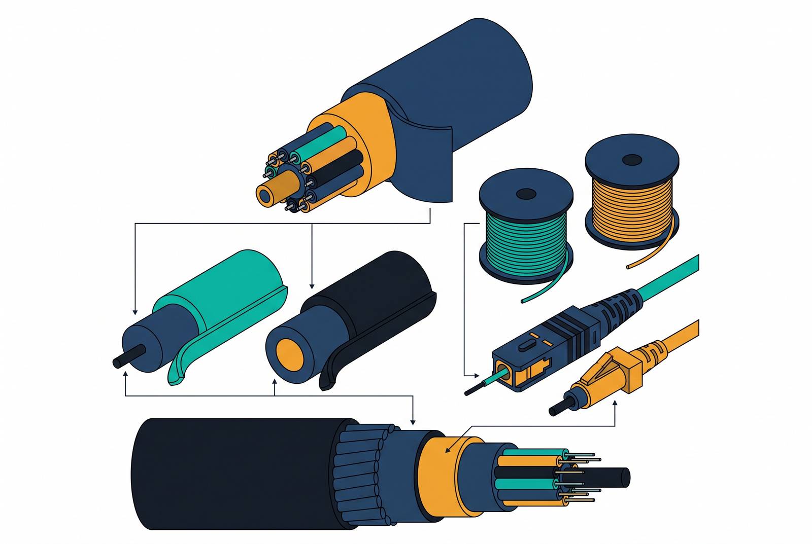
How the ITU-T classification system organizes SMF standards, with OS1/OS2 as a parallel nomenclature, not a replacement
Fiber optic cable comes from a family of ITU-T standards, each one balancing loss, bend tolerance, and reach differently. The standard a provider picks for each layer of the network decides plant performance: it either runs clean for the next twenty years or turns into a re-splicing job halfway through a PON upgrade. Fiber in the ground doesn't get refreshed on a hardware cycle the way a router or an OLT card does. It stays in the ground for the long term, and that single fact should drive every specification decision made before the trench closes. That single fact should drive every specification decision made before the trench closes, and most of the costly mistakes in this industry trace back to someone treating a fiber choice as if it were as reversible as a firmware update.
ITU-T's G-series defines the actual physics of a fiber: its geometry, its mechanical tolerances, its transmission behavior at given wavelengths. OS1 and OS2 describe something else entirely, the cable construction and the environment it's built to survive. Treating one system as a stand-in for the other is where a lot of spec sheets go wrong, and it happens more often than it should.
OS1 is tight-buffered, meant for indoor use only, with reach that tops out in the low kilometers. Nobody should be specifying it for new builds at this point. OS2 is loose-tube, works indoors and outdoors, and with EDFA amplification pushes signal out to 200 km. As of 2026, OS2 is the default for any new deployment, and there's no real argument for anything else.
Confusion in regional labeling comes from a documentation split. U.S. vendors and spec sheets talk in OS1/OS2 terms almost exclusively. European and Asian technical documentation skips that shorthand and names the G-series standard directly: G.652D, G.657A1, G.657A2. Same fiber, same optical performance, different naming convention depending on which side of the ocean wrote the datasheet. A network engineer moving between these documentation styles has to recognize that OS2 and G.652D aren't competing specs. They describe the same cable from two different angles.
G.652: the baseline standard SMF that still dominates backbone and long-haul outdoor plant
G.652, non-dispersion-shifted fiber (NDSF), is what most people picture when they picture single-mode fiber. It's the default for outdoor backbone runs, campus backbone links, and long outdoor hauls where the route doesn't demand tight bends.
The sub-category that matters for anything built today is G.652.D. It carries low water-peak attenuation and works across the wavelengths used in both CWDM and DWDM systems, which keeps it flexible for wavelength-division upgrades down the line.
G.652.D gets you the lowest cost per kilometer of any standard SMF, and it wins on long, straight runs where nothing forces a tight bend radius. It doesn't give you bend flexibility, and that's not a minor caveat. Push it into a cramped conduit, wind it through a drop terminal, or route it through a building where wall cavities and door frames force sharp turns, and it performs badly enough to blow the loss budget.
That's why G.652.D belongs in the feeder segment of an FTTH optical distribution network, in inter-central-office backbone runs, and on long-haul terrestrial routes where the geometry stays forgiving. Anywhere the route gets tight, G.652.D is the wrong call, full stop.
G.657: bend-insensitive SMF, now the default for FTTH drops and premises routing
G.657 takes the G.652 foundation and fixes its one real weakness: bend sensitivity. The two sub-categories that matter for FTTH and premises work are G.657A1 and G.657A2, distinguished by how tight a curve the fiber survives without leaking signal.
G.657A1 holds a minimum bend radius of 10 mm and stays fully backward compatible with G.652 systems, so splice and connector work doesn't need re-testing when extending existing G.652 infrastructure. G.657A2 tightens that radius to 7.5 mm and earns its place in FTTH terminals and dense indoor routing where even A1's radius can't be held. Then there's the B-series, G.657B2 and G.657B3, at 7.5 mm and 5 mm. These bend tighter still but drop backward compatibility with G.652 entirely, which limits them to self-contained premises runs with no legacy splice requirement.
For most FTTH builds today, G.657A1 and A2 are the practical default: low loss combined with bend tolerance that lets installation crews route drops around meter boxes and tight wall cavities without babying the cable. A network running G.652.D in the feeder and G.657A1 in the drop stays splice-compatible end to end, because A1 was built specifically to interoperate with G.652 without forcing a redesign of every splice point along the way. That coherence is worth more over the life of the plant than whatever a slightly cheaper alternative saves upfront.
G.654: ultra-low-loss fiber and where its use case begins and ends for service providers
G.654 solves a different problem than either of the above: ultra-long reach, submarine cable runs, and high optical power handling, achieved through very low attenuation and a larger fiber core.
The trade-off is chromatic dispersion at 1550 nm, and it's steep. G.654 is engineered for systems where dispersion compensation gets designed in from the start, submarine cable and ultra-long terrestrial routes being the obvious cases. It is not a general-purpose backbone upgrade, and any provider who treats it like one has misread what the fiber was built to do.
Its legitimate territory: transoceanic and very long terrestrial links where the loss budget can't close on G.652 and standard amplifier spacing, plus high-power coherent transmission systems built around its specific dispersion profile. That territory ends at the edge of the FTTH ODN, at metro distribution, at any application where that dispersion characteristic turns from a managed design parameter into a liability nobody planned for.
G.655 and nonzero dispersion-shifted fiber: a legacy WDM workaround that matters for upgrade planning
G.655, nonzero dispersion-shifted fiber, was an engineering fix for a problem that mostly doesn't exist anymore: four-wave mixing in dense WDM systems of an earlier generation. It solved that problem well, at the time.
Nobody should be buying it for new fiber procurement today. Where it still matters is in planning, specifically for providers who inherit G.655 routes and have to account for its dispersion behavior when picking transponders and amplifier configurations.
Modern DWDM systems and coherent optics have closed most of the gap G.655 was built to bridge. G.652.D is the stronger choice for any new backbone build, no contest. G.655 is worth understanding when it appears in inherited plant, measured against the standards it was originally installed under. It is not something to spec going forward.
How cable construction (loose-tube vs. tight-buffered) determines where any fiber type can be deployed
Fiber type and cable construction are two separate specifications, and mixing them up causes real failures in the field. A G.652.D core can sit inside either a loose-tube or a tight-buffered jacket, and picking the wrong jacket for the environment breaks the deployment no matter how good the fiber itself is.
Loose-tube construction uses gel-filled buffer tubes to keep moisture and environmental stress off the fiber. It's the standard for backbone infrastructure, campus interconnects, and long outdoor spans, and it's the construction behind OS2-class performance at extended distances. It also supports high fiber counts, which matters on trunk routes carrying hundreds of strands.
Tight-buffered construction trades some of that outdoor resilience for crush resistance and fire rating, which is what FTTH drops, FTTD, and FTTN runs need where cable enters a building or crosses plenum space. It handles the shorter spans typical of last-mile drops fine, but it's the wrong choice for long outdoor routes. Moisture ingress and thermal cycling degrade it over time in ways loose-tube construction is built to resist.
The three-layer FTTH architecture, OLT, ODN, ONT, needs different cable construction at each layer on top of a different fiber grade. Get one right and the other wrong, and the plant still fails.
Mapping fiber types to the three-layer FTTH architecture: feeder, distribution, and drop
A quick recap of the layers. The OLT at the central office generates the optical signal and manages every subscriber connection riding on it. The ODN includes the feeder and distribution cabling, the splice points, and the passive splitters between the OLT and the customer. The ONT sits at the customer premises and terminates the signal.
Fiber selection changes at each layer, and the logic follows straight from what's covered above. The feeder, running from the OLT to the distribution point, calls for G.652.D in loose-tube outdoor cable: long straight runs where cost dominates and bend constraints stay manageable. The distribution segment, from the distribution point to the drop terminal, can run either G.652.D or G.657A1 depending on how tight the conduit routing gets, with G.657A1 earning its cost premium wherever duct paths involve sharp turns or shared infrastructure. The drop, from terminal to ONT, is where bend performance stops being optional: G.657A1 or G.657A2 in tight-buffered construction, A1 preferred when backward compatibility with the feeder splices matters, A2 reserved for the tightest indoor routing.
This layering isn't only about today's loss budget. With a coexistence element in place, 50G-PON architecture can run GPON, XGS-PON, and 50G-PON over the same fiber plant at the same time, and the fiber chosen now has to accommodate that upgrade path without a re-pull. G.657A1 at the drop, sitting on top of G.652.D in the feeder, keeps the whole ODN splice-compatible as the active equipment generations turn over. Getting the standard right the first time matters precisely because nobody is re-trenching a residential street to swap fiber grades when the next PON generation ships.
Fiber specifications for Carrier Ethernet and dedicated internet access infrastructure
Carrier Ethernet services, Ethernet DIA, Ethernet Private Line, Ethernet Virtual Private Line, Metro LAN, WAN VPLS, all ride on the same fiber infrastructure covered above, and their SLAs are constrained directly by that plant's loss budget and dispersion characteristics. A service can't deliver a tighter service-level agreement than the fiber underneath it supports, no matter what the sales sheet promises.
DIA holds the top position among providers in one country's market for Carrier Ethernet services by both port count and revenue, and delivering on that means the fiber underneath has to meet the loss budgets and availability numbers enterprise customers contract for. MEF 3.0 certified Carrier Ethernet services depend on the transport layer beneath them holding up its end. Fiber quality and construction are the foundation those service parameters get built on, and there's no substitute layer that compensates for a bad choice made at the trench.
For metro and regional Carrier Ethernet routes, G.652.D in loose-tube outdoor plant is the standard, and nothing else really competes for that role. G.654 has no place at this layer; its dispersion profile and submarine-grade design solve a different problem. G.657 becomes relevant only where fiber enters the customer premises as part of a dedicated access circuit, where its bend tolerance earns its place the same way it does in FTTH drops.
The operational costs of poor fiber specification decisions and how OSS visibility closes the gap
Fiber specification mistakes rarely become visible at the point of installation. They become visible weeks or years later, in operations, and they're expensive precisely because nobody flagged them earlier.
Bend-radius violations are the most common failure: G.652.D installed where G.657 was called for, discovered only when signal loss spikes at service activation and a truck has to roll out to re-pull cable that should have been specified correctly the first time. Construction mismatches cause a different kind of headache. Outdoor loose-tube cable terminated indoors without a proper transition lets moisture in, and this becomes visible later as an intermittent fault, one of the hardest failure modes to diagnose without accurate records of what's actually in the ground. In inherited or acquired plant, undocumented fiber type is its own trap: integration planning defaults to the wrong splice and connector assumptions, and activation fails for reasons nobody can trace quickly.
All three failures share the same root cause. Fiber type, construction, and location need to get captured accurately in the OSS data model at build time, not reconstructed later during fault isolation, and most operators still get this backward. An OSS platform that connects premise data, network records, provisioning, and activation on one shared data model lets orders move forward automatically based on verified plant state, but that automation is only as good as the fiber records feeding it. An OSS built on a single data layer spanning qualification, design, provisioning, and activation catches a fiber-type mismatch during qualification, before a truck ever gets dispatched, because the fiber record, the service design, and the activation workflow are all reading from the same source instead of three disconnected systems that each think they're right.